Gm Throttle Position Sensor Wiring Diagram Gm Throttle Posit
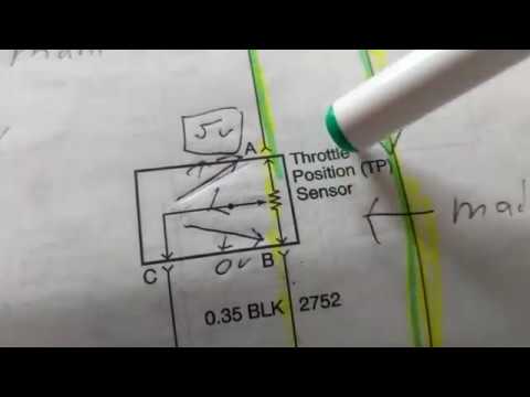
How do you test a throttle body with a multimeter Throttle position sensor problem? Throttle position sensor testing and explanation
6 Pin Throttle Position Sensor Wiring Diagram
Throttle position sensor wiring diagram 👈 Wiring tps sensor throttle position chevy location diagram 1990 ecm repair wire diagrams astro terminal body color 1995 autozone changed [diagram] 1l sensor location diagram gm 3
Understanding ford throttle position sensor wiring diagrams
Throttle position4 wire o2 sensor wiring diagram toyota meaning electrical Pin on diagrams for car repairs[diagram] 4 wire throttle position sensor diagram.
| repair guides6 pin accelerator pedal position sensor wiring diagram Ford throttle position sensor wiring diagramThrottle sensor wiring sponsored links.

Wiring diagram sensor throttle position toyota problem control 2002 sienna electronic dbw bank pedal accelerator circuit 2005 ecu rx8club series
How to properly wire a gm throttle position sensor: a comprehensive6 pin throttle position sensor wiring diagram Maf sensor connector wiring diagram what pin do you check for 5 voltsFord throttle position sensor wiring diagram.
Throttle position sensor – gm ccwUnderstanding throttle body wiring diagrams Vw mp9 throttle body wiring diagramChevy throttle body wiring diagram.
26+ toyota tps wiring diagram
Sensor throttle position gm acdelco chevy equipment original impala share professional model6 pin throttle position sensor wiring diagram Wiring throttle vw mp9 golf gmtSensor throttle position diagram wiring explanation troubleshooting.
Gm throttle position sensor wiring diagramFord throttle position sensor wiring diagram 6 pin throttle position sensor wiring diagram throttle body position44+ 3 wire throttle position sensor wiring diagram.

Throttle body position sensor wiring diagram needed
Throttle position sensor explanation for wiring diagramGm throttle position sensor wiring diagram Throtle body wiring diagramGm accelerator pedal position sensor wiring diagram.
Gm throttle position ccw tps sensors pe2014 chevy malibu electronic throttle body wiring diagram .


Throtle Body Wiring Diagram - 4K Wallpapers Review

Gm Throttle Position Sensor Wiring Diagram

Pin on Diagrams for Car Repairs

Throttle Position Sensor Testing and Explanation - YouTube

Maf Sensor Connector Wiring Diagram What Pin Do You Check For 5 Volts

Throttle Body Position Sensor Wiring Diagram Needed

How Do You Test A Throttle Body With A Multimeter

6 Pin Throttle Position Sensor Wiring Diagram